Galvanzied steel plate Galvanzied steel plate Shandong Longhao Steel Group Co., Ltd. , https://www.longhaoss.com

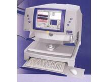
Electroplating thickness gauges, divided into magnetic induction coating thickness gauge, eddy current coating thickness gauge, fluorescent X-ray coating thickness gauge. Early products use an analog meter to measure the magnitude of the induced electromotive force. The instrument amplifies the signal and then instructs the thickness of the coating. In recent years, circuit designs have introduced new technologies such as frequency stabilization, phase lock, and temperature compensation, and use magnetic resistance to modulate measurement signals. It also uses a patented integrated circuit designed to introduce microcomputers to greatly improve measurement accuracy and reproducibility (almost one order of magnitude). The magnetic principle thickness gauge can be used to accurately measure the paint layer on the steel surface, porcelain, enamel protective layer, plastic, rubber coating, all kinds of non-ferrous metal plating layer including nickel and chromium, and various anti-corrosion coating for chemical oil industry Floor.
In our actual measurement work, the following factors affect the measurement of the electroplated coating thickness gage:
(1) The surface roughness of the workpiece is too large, which results in poor coupling between the probe and the contact surface, low reflection echo, and even failure to receive echo signals. For surface corrosion, the in-service equipment and pipelines with poor coupling effect can be treated with sand, grinding, and contusion to reduce the roughness. At the same time, oxides and paint layers can be removed to expose the metallic luster. Coupling agent can achieve a good coupling effect with the test object.
(2) The radius of curvature of the workpiece is too small, especially when measuring the thickness of a small tube. Because the surface of a commonly used probe is a plane, contact with a curved surface is point contact or line contact, and the sound intensity transmittance is low (coupling is not good).
(3) The detection surface is not parallel to the bottom surface, and the acoustic wave encounters scattering on the bottom surface. The probe cannot receive the final wave signal.
(4) castings, austenitic steel due to uneven microstructure or grain size, ultrasonic waves in which to pass through when there is a serious scattering attenuation, scattered ultrasonic waves along a complex path, there may be echoes annihilation, resulting in no display .
(5) The probe contact surface has a certain amount of wear. The commonly used thickness measurement probe surface is acrylic resin, and its long-term use will increase the surface roughness, which will result in a decrease in sensitivity, resulting in incorrect display. 500# sandpaper can be used to sand the periphery of the probe to make it smooth and ensure parallelism. If it is still unstable, consider replacing the probe.
(6) There is a large amount of corrosion pits on the back of the measured object. Due to rust and corrosion pits on the other side of the test object, sound waves are attenuated, resulting in random readings and no reading in extreme cases.
(7) There are deposits in the measured object (such as pipeline). When the acoustic impedance of the sediment and the workpiece are not much different, the thickness gauge shows the wall thickness plus the thickness of the deposit. For example, the scale inside the pipeline is in close contact with the pipeline.
(8) When there are defects inside the material (such as inclusions, interlayers, etc.), the displayed value does not agree with the thickness value. At this time, the ultrasonic flaw detector can be used for further defect detection.