1. Proposed issue 3. Experiment 4 Conclusion Concentrated sulfuric acid electromagnetic flowmeter acid liquid flowmeter sewage flowmeter ammonia electromagnetic flowmeter Led Toaster,Kitchen Toaster Oven,Kitchen Toaster,Electric Toaster Evergreen Houseware , https://www.evergreenhome.cn
After the fluid flows through the elbow, the distribution of the flow velocity in the downstream is distorted. If there are two different plane elbows adjacent to each other, there will be vortices in addition to the flow distribution distortion. These phenomena must affect the measurement values ​​of most types of flow meters installed downstream (except for a few types such as positive displacement). Therefore, it is usually required to have a straight pipe section of a certain length before the installation point of the flow meter to improve the flow conditions of the incoming meters. Electromagnetic flowmeters are less affected by bends, and straight pipe length requirements are much lower than other flowmeters, such as throttling differential pressure, vortex-type, etc. However, the accuracy of the current electromagnetic flowmeter is 0.5% or even 0.2% to 0.4 of the measured value. Even if the influence is small, it is still concerned by people.
In addition to the straight pipe section before the meter can reduce the impact of the bend, people also managed to reduce the impact of the installation method. In [1], it has been reported that the electrode axis of the electromagnetic flow sensor is 45 with the adjacent elbow plane.
Tilt installation can reduce the effects of bends. Japanese Industrial Standard B7554 "The commentary section" lists the axis of the electrode perpendicular to the plane of the elbow, parallel to 45. Three kinds of installation methods, in the measurement error range under different lengths of straight tubes, also illustrate this effect. . In 2000, Shanghai Yuanshui Company planned to install a DN2200 electromagnetic flowmeter in a pump station that has already been built, but the length of the straight pipe at the downstream installation position of the elbow pipe obviously did not meet the requirement of 5D to 10D in the regulation (D is the pipe diameter, the same below). At this time, what is the impact of measurement error? Due to the limitations of the conditions, it is impossible to use the classic measurement method (such as the flow velocity area method) for the comparison test to estimate the additional error value of the bend. And the user must know the additional error estimate before ordering to determine the design plan. According to the similar principle, the author uses a smaller diameter electromagnetic flowmeter to test the field conditions in the laboratory. Test proved 45. Installation can reduce the effect of bends. The impact value of the traditional installation method under the installation condition of the case was obtained.
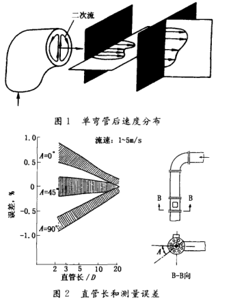
2. The distribution of flow velocity in the downstream of the elbow affects the flow of fluid through the elbow due to the centrifugal force. It produces a diffusion effect on the outer wall and a contraction effect on the inner wall. This results in a secondary flow in the transverse flow, which causes a distortion of the velocity distribution in the downstream, as shown in Figure 1. .
In Figure 1, the outer edge of the right-hand section of the elbow has a faster flow velocity, and the horizontal section shows a double-peak flow velocity distribution. As the flow leaves the elbow, the distance increases. Distortions tend to ease.
Most current electromagnetic flow sensors are non-uniform magnetic field distribution structure designs. According to the theory of non-uniform magnetic field, the measuring tube containing the electrodes in the cross-sectional area, each tiny liquid volume element cutting magnetic force line “differently†acts on the inter-electrode signal, and thus is not uniformly but “uniquely†non-uniformly. The magnetic field strength at each point is designed so that the distortion of the flow velocity distribution under ideal conditions does not affect the flow measurement value. However, the actual instrument still suffers some effects. Figure 2 shows the error range of different straight pipe lengths for the three installation methods downstream of the Japanese industrial standard's attached bend. 
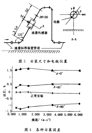
The real-flow experiment was conducted on the water flow standard device for weighing method of Shanghai Guanghua Ai Meite Instrument Co., Ltd. The uncertainty of the device is 0.011. The test instrument is the IFM4080K type of DN100. The pipeline is reduced according to the proportion of the field geometry. The calibration is carried out on the standard equipment as shown in Figure 3. The test results are shown in Figure 4. In the figure, "normal installation" means that the length of the straight straight pipe section is greater than or equal to 10 D, and the length of the straight straight pipe section is greater than or equal to 5 D. The test data is the reference value. The electromagnetic flowmeter has a full flow of 150m. /h, experimental flow rates ranged from 0.32 to 5.3 m/s. A total of 5 flow points were made. 
1) In the test installation conditions, the flow sensor electrode shaft is at A-90. The maximum error in position is 1.2, A-0. The position is +1.6, A 45. The position is 0.5; the maximum additional error is A - 90 compared to the normal installation condition that is the reference value. The time is 1.2 and A==:0. It was +1.65, A 45. It is +0.65.
2) Experiments demonstrate electrode axis 45. The installation is much better than the traditional horizontal installation (A-o.) bending flow disturbance.
3) Even if the electromagnetic flow sensor has a sufficiently long (5D) straight pipe section downstream of the bend pipe, “45. Installation†shall be used as a measure to reduce the influence of the bending flow of the bend pipe and reduce the additional error.