Suspended platform, as temporary suspended cradle platform, are
widely applied in maintenance applications such as curtain fecade
cleaning in high rise building, painting, glazing repairs, bill- board
painting, cable installation and other outer working of high rise
building up to 150 meters about 30 floors high. Our ZLP series suspended
platform cradle, ZLP1000, ZLP800, ZLP630, ZLP500, ZLP400 and ZLP150, are
good choices for fulfill above outside of wall work. Based on the different materials, the suspended platform could be divided into Aluminum Working Platform, steel Working Platform, galvanized Working Platform.
ZLP series temporarily installed suspended platform is an ideal access equipment for building facade construction, decoration, cleaning and maintenance. It can be also applied to other aerial working such as elevator installing, ship building, construction of dam, bridge, large chimney, etc.
This equipment is easy to operate, convenient to move and reliable in safety and much more efficient than traditional scaffolding.
Suspended Working Platform,Suspended Cradle Platform,Aluminum Working Platform,Suspended Construction Platform,Working Platform Cradle SHEN YANG BAOQUAN BUSINESS CO., LTD , https://www.sczenghui.com


Â
Main Applications:
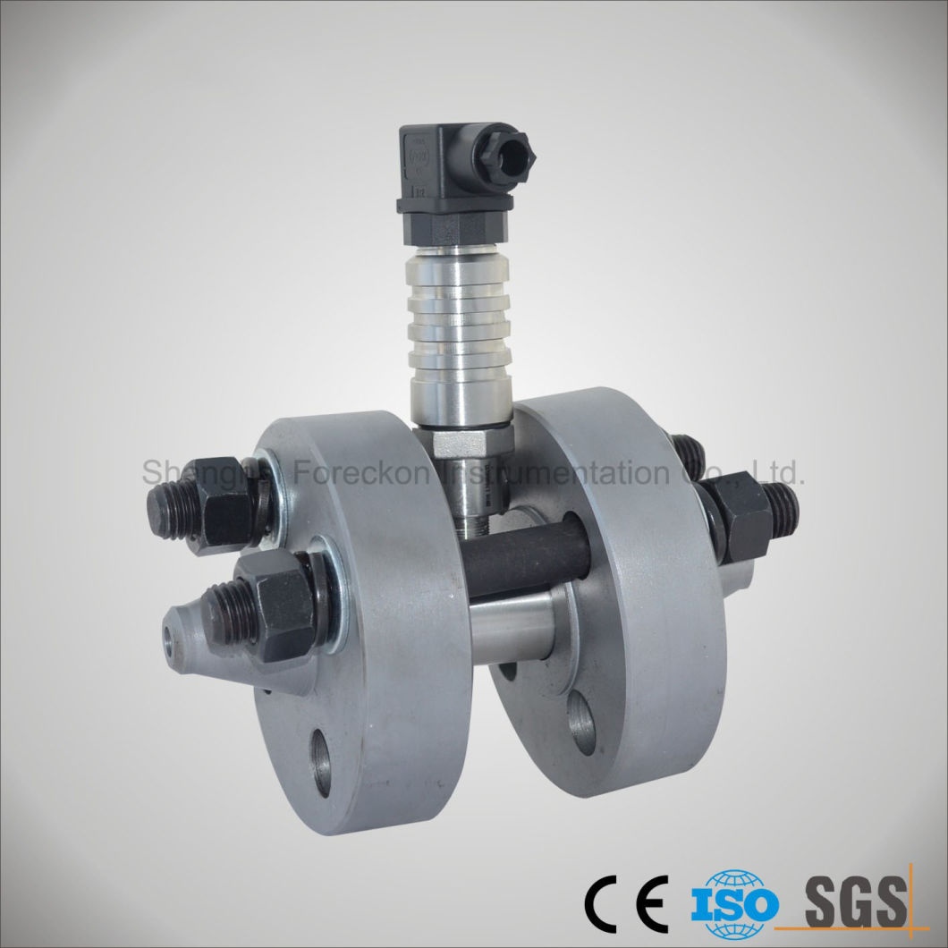
Turbine flow flowmeter adapts to measure the liquid rate and total flow rate of low viscosity, It can be widely used in the fields of Petrol,fuel ,water ,chemical industry,Metallurgy,Scientific research for measuring or control Several output and display methods can be selected.
Â
Features:
- Pulse output, linear feature;
- High accuracy, sensitive reaction;
-Wide measuring range;
-Signal output
- Simple structure, easy installation, operation and maintenance;
-Filter, eliminator and rectifier(aligner) can be provided as a whole package;
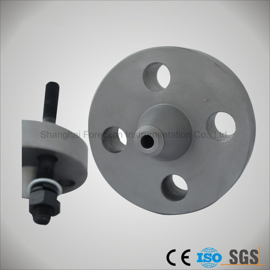
- A pair of companion vice flanges for installation is available.
Â
Technical parameters:
Table 3-1
Nominal Diameter
DN(mm)Range(m3/h)
Liquid Temperature
(ºC)Nominal Pressure
PN(MPa)Ambient Temp.
(ºC)Humidity
(%)Max. Pressure Loss
(MPa)
Error Â
0.2%*Error   0.5%
Error     1%
Min.
Max.
Min.
Max.
Min.
Max.
2*
Â
Â
Â
Â
0.03
0.16
-20
 to
+1206.3
-25
to
+55≤ 80
0.15
4*
Â
Â
Â
Â
0.04
0.25
0.12
6
Â
Â
0.1
0.6
0.1
0.6
6.3
16
25
32*0.08
10
Â
Â
0.25
1.2
0.2
1.2
0.05
15
1.2
6
0.6
4
0.6
6
0.035
25
2
10
1.6
10
1
10
40
4
20
3
20
2
20
1.6
2.50.025
50
6
40
4
40
4
40
80
16
100
10
100
10
100
100
25
160
20
160
20
200
1.6
2.5
150
50
300
40
300
40
400
200
150
750
100
600
80
800
250*
200
1000
160
1000
120
1200
1.6
300*
Â
Â
260
1600
180
1800
Â
Table 3-2 Model and Specification Code
Model
Specification Code
Description
LW.......................................................................................
Turbine Flowmeter
Transducer
For Liquid
Â
G........................................................................
Â
Y......................
Nominal Diameter
-2*.................................................
-4*.................................................
-6..................................................
-10................................................
-15................................................
-25................................................
-40................................................
-50................................................
-80................................................
-100..............................................
-150..............................................
-200..............................................
-250..............................................
-300..............................................2mm(PT G3/8″)
4mm(PT G3/8″)
6mm(PT G3/8″)
10mm(PT G1/2″)
15mm(PT G1″)
25mm(PT G11/4″)
40mm(Flange)
50mm(Flange)
80mm(Flange)
100mm(Flange)
150mm(Flange)
200mm(Flange*)
250mm(Flange*)
300mm(Flange)
Type Code
A............................ ..........
B............................ ..........
C............................ .......Accuracy 1%
Accuracy 0.5%
Accuracy 0.2%*
Output Signal
P......................... .......
I.......................... .......
T......................... .......
M........................ .......Pulse
Analog 4 to 20mA
Total display(Battery. for 2 to 3 years)
Pulse out/4 to 20mA out and LCD display(Intelligent)
Diameter Pressure
C1................... .....
C2................... .....
C3................... .....
C4................... .....
C5................... .....
C6................... .....
C7................... .....PN1.6MPa
PN2.5MPa
PN4.0MPa
PN6.3MPa
PN16MPa(Diameter≤25mm)
PN25MPa(Diameter≤25mm)
PN40MPa*(Diameter≤25mm)
Explode Request
/NE
/EXNot Explosive
Ex ib I or Ex dIIBT4
Range of Temperature
/NT
/HTNormal Temperature(<120ºC)
High Temperature(≥120 to 150ºC)
Special Option
/
e.g.:High Temperature,Erode-resistant,Wearable etc.
Â
Â
Â
Â
Â
Â
Â
Â
Â
Â
Â
Â
             2. Mark "*" means apecial order.
Â
Model NO.: JH-LWGY-HP
Measuring Media: Liquid
Measuring Principle: Mechanics
Measurement Object: Closed Pipeline
Certification: CE, RoHS, ISO
Display: None
Temperature: -20c~120c
Power Supply: 24VDC or Battery
Output Signal: 4-20mA, Pulse, RS485
Body Materia: Ss304/Ss316
Connection: Flange or Screw Thread/Hausman
Pressure: 25MPa
Trademark: JH
Transport Package: Carton/Wooden Case
Specification: CE, ISO
Origin: Shanghai
HS Code: 9026100000
Â
Liquid Turbine Flowmeter