SCR trigger circuit SCR, also called thyristor, is a high-power semiconductor device that can control and transform high-power power with small signal power. SCR is divided into one-way thyristor, two-way thyristor, thyristor can be turned off and fast thyristor, etc. According to functional requirements, this design chose one-way thyristor. SCR trigger circuit, Vin introduces the engine ignition signal. When the signal is high, after over-voltage and over-voltage protection of the resistor and capacitor, the input voltage to the control terminal of the thyristor, the voltage is about 2V, so that the thyristor's anode and cathode conduct, also makes Vi ground , and thus linked with the subsequent circuit, to achieve the flash of electronic flash. When the Vin signal is low, Vi is cut off and the flash does not light up. The step-up circuit of the flyback DC-DC step-up circuit electronic flash is actually an intermittent oscillator, and the return time is mainly determined by the operating status of the intermittent oscillator. The smaller the inductor, the faster the charge; the smaller the turns ratio, the greater the primary cut-off current, so the greater the average operating current. The flyback DC-DC boosts the routing diodes, transistors, resistors, and boost coils in this article. Its function is to transform the DC voltage of 12V into an AC voltage of about 30V through the oscillating circuit, and then after the boost coil, the AC voltage is raised to the upper KV (about 1.8KV), after the subsequent diodes D2, D3 and the capacitor C3, The filter shaping of C4 changes the AC voltage back to DC voltage. At this time, the output DC voltage is about 340V, and the DC voltage across the resistor is about 180V, which satisfies the two voltage values ​​required by the electronic flash. The electronic flash circuit can be divided into several types such as Xe, MF, and FP according to the characteristics of the flash light source from the beginning of ignition to the end of light emission. The main application is the spectral distribution of the Xe electronic flash and the Xe electronic flash. Similar to natural white light, the color temperature is about 5700K, suitable for color photography, and high luminous efficiency. The output light energy of this type of electronic flash is proportional to the input power, and the input power E is also proportional to the capacity of the charging main capacitor C6 and the charging voltage. This design uses the Xe type electronic flash. When the flyback DC-DC step-up circuit outputs a voltage of about 340V to the 3rd and 4th terminals, the charging main capacitor C6 is automatically charged and the voltage across the resistors R5 and R6 is divided so that the voltage across the capacitor C5 is about 180V when Vi is grounded. When the capacitor C5 and the trigger coil T2 form a loop, the trigger coil T2 will generate a high voltage pulse of 10KV and introduce the high voltage to the flash. At the same time, the main capacitor C6 discharges the flash of the electronic flash to make the flash of the electronic flash fire. Required indication function. When Vi has no signal input, that is, when it is open circuit, the circuit returns to normal and the flash does not flash. Timing meter debugging After connecting the components according to the circuit diagram, the electronic flash is always on and the brightness is low, and the power resistance is particularly hot. Found that the voltage on both sides of the electronic flash is insufficient, and the main capacitor C6 stability is not good enough. The reason is that C6 uses a polypropylene capacitor (CBB), and its performance is similar to that of a polystyrene capacitor (CB), but its stability is poor. After CB is replaced with CB, the voltage is appropriately increased and the problem is solved. Since the duty cycle t = nrc (n is a constant, c is the capacitance, r is the resistance of the resistors connected in series), the larger the capacitance, the longer the charging and discharging time, and the highest operating frequency that can be achieved. The lower the capacitance, the greater the capacity of the capacitor, the greater the output light energy and the higher the brightness. After testing, when the capacity of C6 is 1μf, the frequency limit of the flash is about 40Hz, and when the capacity is 3.3μf, the frequency limit of the flash is about 9Hz, but the brightness is obviously larger than the capacitance value of 1μf. The operating frequency required by this design is more important than the brightness, so the capacitor with a capacity of 1μf and a capacity of 400V is used as the main capacitor. A distributor's ignition system (with high-voltage lines) tests the timing instrument using an already calibrated test system. The absolute error of the simulation device in the test system is ±0.18 Hz and the relative error is ±0.21%. The absolute error of the feedback device is ±0.28Hz, and the relative error is ±0.34%. Among them, the simulation output high-voltage line can provide a signal source for the detection of the timing instrument, and the frequency is adjustable in the range of 1 to 80 Hz (corresponding to the crankshaft rotation speed of the four-cylinder gasoline engine is 120 to 9600 rmin-1, which satisfies the normal automobile normal rotation speed range).
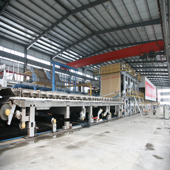
The fourdrinier Paper Making Machine is mainly used for making top grade corrugated base paper, test liner paper,medium paper, high quality light-weight paper (culture paper, newsprint, light weight specialty paper). This kind of peper machine needs to chosse papermaking type, dewatering structure of press section, arrangement of dryer cylinder group, sizing and finishing equipment according to different paper grades and operating speed requirements.
Paper Machine,Paper Product Making Machinery,Liner Board Paper Machine,Test Liner Paper Machine Dandong Tianshin Automatization Technology Co.,Ltd , https://www.ctpmmachine.com