Keywords: micro flow, micro-combustion, liquid flow meters, gas flow meters, micro-electromechanical At present, MEMS devices are attracting more and more attention of scholars. At the 1989 meeting in Salt Lake City, USA, the MEMS concept was first proposed: Micro -Electro-MechanicalSystems, that is, microelectromechanical systems, which refers to devices that feature electronic devices and mechanical devices with feature sizes ranging from 1 μm to 1 mm. The study of micro-combustion is the basis for the manufacture of micro-electromechanical devices, and the precise measurement of micro-fuels is a prerequisite for the experimental study of micro-combustion. Micro-flow measurement and control system is an important direction of micro-mechanical research, and it is also a major technical measure of micro-fluidic precision measurement and control. The technical background of the microfluidic system research is the maturity of micromachining technology, and the application background is the special occasion that the flow and viscosity requirements of some conventional fluid systems cannot meet. After the micro-flow system has matured, it can even replace some of the current products. The flow rate of the microfluidic system is in the order of nL/min~L/min. Due to the small size, the system can reduce the ineffective volume, reduce energy consumption, and increase the response speed.
In the preliminary micro-scale diffusion combustion experiments, we have a preliminary understanding of all aspects of the micro-flame characteristics. As experiments are carried out in more detail, accurate measurement of micro-flows will be a critical link. Because the error between the actual supply value and the measurement value of the micro flow will directly affect the accuracy of the experimental results. Although researches on micro-flow measurement at home and abroad started relatively late, with the deepening of theoretical research and the accumulation of practical experience, there is a more concrete and profound understanding of the difficulty and existing problems of micro-flow measurement, through continuous improvement. With perfection, micro-flow measurement technology has been continuously developed.
1 The measurement of liquid micro-fuels The flow rate of domestic liquid flowmeters on the market can only reach a few hundred milliliters per minute. Imported flowmeters generally have a minimum flow rate of tens of milliliters per minute, but they are expensive; however, standard differential pressure flowmeters are generally used. Plate hole type, nozzle type, Venturi tube type, etc., its rated flow is larger, measurement accuracy is lower, usually the error is more than 5%. Can not meet the requirements of liquid micro flow metering.
1.1 Thermal Liquid Mass Flow Meter The experts of the Flow Meter Association of China Instrument Industry Association have provided an overview of the measurement principle, performance and application of thermal flow meters.
Thermal flow meter from the measurement principle, can be divided into two categories: 1) the use of flowing fluid to transfer heat to change the wall temperature distribution of the measurement of the heat transfer distribution effect of the heat distribution flowmeter, formerly known as calorimetric flowmeter; 2 ) The thermal Mass Flowmeter, which uses the heat dissipation (cooling) effect of the Kim's Law, is characterized by the insertion of a temperature measuring element into a measuring tube or pipe of a flow sensor, called an insert type thermal flow meter. However, the existing liquid micro flow thermal flowmeters are thermal distribution flowmeters.
Fig. 1 is a schematic diagram of the heating type thermal flowmeter, and Fig. 2 is a refrigerating type schematic diagram using the Peltier effect. The types of heated thermal liquid mass flow meters on the market include Liqu-iFlow and L-Flow models from Bronkhorst H-iTech in the Netherlands, and Flomega models from Brooks in the United States; and refrigerated thermal liquid mass flow meters on the market. The LF series of the American Estech company is seen. There are 9 full-scale specifications in the range of 0.01g/min~100g/min, and the response time is about 2s. Thermal liquid mass micro flowmeter is suitable for measuring liquid gas, mixing ratio of liquid medicine, raw material gasification supply system. Volume flow rate is as small as 10-6L/min~10-3L/min, or mass flow rate is 10-6kg/min~10-3kg/min.
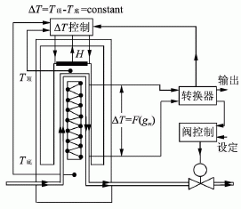
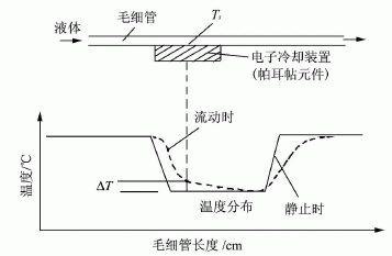
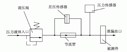
FIG. 3 shows a structural block diagram of a tubular differential pressure flowmeter detecting the water leakage of the thermostat. The flowmeter consists of a long throttle tube and a differential pressure sensor. In Fig. 3, the device under test is a thermostat for automobiles. It is necessary to detect the relationship between the water pressure applied to the thermostat and the magnitude of the leakage when the valve of the thermostat is closed. In order to make the pressure difference on the flow meter not affect the detection, the input pressure detection sensor of the device under test is placed at the inlet of the pressure liquid of the tested part. The input pressure of the tested part is provided by the pressure liquid and the pressure regulating valve; adjusting the pressure regulating valve can apply a series of different pressure values ​​to the tested part. The pressure value of the device added to the device under test is pj, the outlet pressure of the pressure regulator valve is pt, and the indicated value of the flowmeter differential pressure sensor is Δp. If line pressure loss is not taken into account, pt=Δp+pj. Since there is a certain relationship between the differential pressure value Δp and the flow rate at both ends of the flowmeter, the relationship between Δp and pj actually reflects the relationship between the leakage amount and the pressure of the device under test.
The specific application method is shown in Figure 4. The capillary tube with known internal diameter and length parameters is cascaded into the flow, differential pressure sensor is used to measure the pressure difference at both ends of the capillary, and then the capillary flow equation can be used to calculate the exact flow of liquid in the flow.

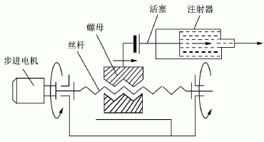
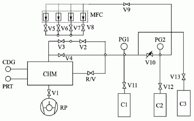
2 The measurement gas flow rate of gas micro-fuel is the amount of gas that passes through a certain section in a unit time. The state of the metered gas flow is described by three parameters: pressure, volume, and time. There are three methods for measuring the gas flow rate: if the gas pressure remains the same, by changing the gas volume measurement method, it is a constant pressure method; if the volume remains unchanged, by changing the pressure measurement method, it is a constant volume method; if Pressure and volume are changing, it is pressure change varactor method. It can be seen that according to the method of flow measurement, it can be divided into constant pressure flowmeter, constant volume flowmeter and variable pressure variable flowmeter. The variable-capacity variable-capacity flowmeter has a complex structure, is difficult to control, and has few practical applications. Generally, a constant pressure type flowmeter and a constant volume type flowmeter are used.
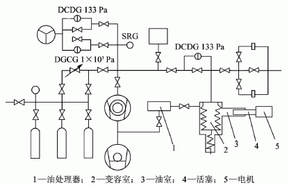
2.1 Constant Pressure Flowmeter Figure 6 shows the schematic of the constant pressure gas micro flowmeter. The constant pressure gas micro flowmeter can provide micro gas flow in the range of 3.96×10⁻⁴Pa•m3/s~3.64×10-8Pa•m3/s. The relative standard uncertainty in the range of 10-8 Pa•m3/s is 1%, and the relative standard uncertainty in the range of 1×10⁻⁷Pa•m3/s~1×10-4Pa•m3/s It is 0.7%. The principle of flow measurement is that when the gas flows into or out of the chamber, the capacity of the chamber is changed so that the gas pressure in the chamber is kept constant, then the flow of gas at Tr temperature (Tr is generally 23°C) can be passed. The pressure P, temperature T, and volume change rate dV/dt of the gas in the chamber were measured and calculated.
Q=-[d(P•V)/dt]•(Tr/T)=-P•(dV/dt)•(Tr/T)(dP/dt=0),(1)
Where: Q is the gas flow rate, unit: Pa•m3/s; P is the chamber pressure, unit: Pa; dV/dt is the volume change rate of the chamber, unit: m3/s; Tr/T is variable Room temperature change rate, dimensionless.
Pattern disc for Warp Knitting Machine is a circular disk that is used to control the movement of the needles on the machine. It is typically made of metal or plastic and has a series of holes or slots around its circumference.
The pattern disc is mounted onto the machine and rotates continuously as the machine operates. As the needles move across the warp yarns, they are guided by the pattern disc, which determines the specific pattern or design that is being created.
Different pattern discs can be used to create a wide variety of designs, from simple stripes and checks to more complex geometric shapes or intricate lace patterns. The choice of pattern disc depends on the desired outcome and the type of yarn being used.
Pattern discs can be customized or purchased pre-made, and they are an essential component of warp knitting machines used in the textile industry.
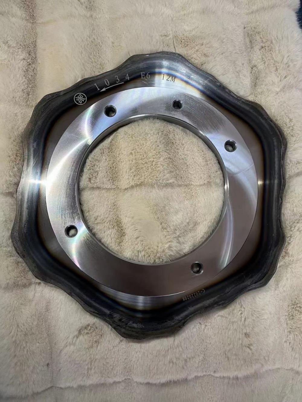
Pattern Disc,Crochet Disc,Crochet Flying Disc,Knit Frisbee Pattern
suzhou cotex international Co.,Ltd , https://www.macanol.com